About
The National Metrology Institute of South Africa (NMISA) has as its central objective; the maintenance of South Africa’s standards and measurements systems and their dissemination throughout the country. In the field of Dimensional measurements, NMISA reproduce the SI definition of the metre and maintains a series of secondary standards which are used in the calibration of equipment submitted by industry.
The National Standards for length in South Africa is the Iodine-Stabilised Helium Neon laser, stable to 2 parts in 10-11, as published in the Government Gazette.
Stated uncertainties quoted, are based on a standard uncertainty multiplied by a coverage factor of k = 2, which, unless specifically stated otherwise, provides a level of confidence of approximately 95%.
In the CMCs uncertainty statements, the notation Q[a; b] stands for the root-sum-square of the terms between brackets:
For all uncertainties of accredited parameters please refer to the SANAS website
SANAS
Measurement Uncertainty
The uncertainties stated in the calibration certificates may differ from the uncertainties quoted, for the following reasons:
- The quality of the Standard under Calibration.
- The environment under which the calibrations were performed.
It is important to remember that the standard under calibration is used under different conditions than when it was calibrated. The temperature, support conditions and differences in the measuring equipment will influence the readings and additional uncertainties will generally occur.
All calibrations are carried out in an environment controlled to a temperature of 20° C ± 1º C and a relative humidity of 45 % ± 15 %, unless otherwise stated.
Figure 1: Capabilities of laboratory illustrated with the range and the uncertainty.
Key Facts
Laser Calibrations
The frequency of single-mode frequency-stabilised lasers can be calibrated by reference to the iodine-stabilised He-Ne laser. Measurements are made by a beat frequency comparison between the test and reference laser. With this technique, the beams from the reference and test laser are combined and focussed onto a detector. The resulting beat frequency signal is the difference frequency between the two lasers, and allows calibration of the test laser. This calibration service is available for 633 nm (red) lasers.
Laser interferometer displacement calibrations are done by direct comparison against a standard laser interferometer. Displacements of up to 10 metres are calibrated.
Velocity of Light Compensation: The air temperature, pressure and humidity sensors of laser systems can be calibrated by the appropriate laboratories
.PNG)
Figure 1; Standard for length in South Africa, the iodine stabilised HeNe laser(Winters system).
End Standards Up To 300 mm (Gauge Blocks)
The NMISA accepts steel, tungsten carbide and ceramic gauge blocks for calibration which are classified as Grade 00, 0, Calibration or Reference grades, Grade 1 and 2. Gauge block accessories are not accepted for calibration. The NMISA is capable of calibrating both metric and imperial gauge blocks.
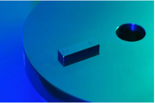
Figure 2; A gauge block wrung onto steel platen.
A Gauge Block Interferometer, which uses two lasers; red and green, is currently used for the calibration of Grade 00 and grade 0 gauge blocks.
Each gauge is measured by wringing the measuring surface to a tungsten carbide base plate and determining the perpendicular distance from the base plate surface to the centre of the exposed face. The practical length is derived from the mean value of two measurements with each face wrung to the tungsten carbide base plate in turn. The value for the coefficient of thermal expansion will depend on the material of the gauge block.
End Standards Up To 1000 mm (Length Bars)
Length bars with rectangular, square or circular cross-sections are calibrated. The NMISA is capable of calibrating both metric and imperial length bars. Bars with nominal sizes between 100 mm and 1000 mm are calibrated on the Length Bar Measuring Machine using a Hewlett Packard laser measurement system, traceable to the National Standard of Length; the Iodine Stabilized He Ne Laser. The bar is supported in a horizontal position at the “Airy points”. Corrections are made for the variation of the laser wavelength with ambient atmospheric conditions and the length of the bar is corrected to 20 °C.
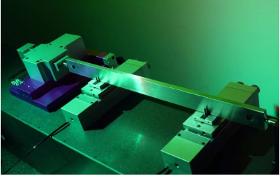
Figure 3; One metre Length bar on length bar measuring machine.
External and Internal Diameter Standards
External and Internal diameter standards are calibrated on a Pratt and Whitney Lab Master. Measurements are achieved by gauging probes which are moving on a virtually frictionless air slide. The relative position of the probes is then detected by a laser interferometer when gauge blocks are used as standards.
Internal diameter standards are calibrated for diameter, and roundness. Diameters of nominal sizes between 5,0 mm and 250 mm are calibrated using the Pratt and Whitney Lab Master. External diameter standards in the form of discs, plugs or thread wire cylinders which may or may not be supported between centres are calibrated for diameter and roundness. Plug gauges of nominal sizes from 0,1 mm diameter up to 330 mm diameter can be calibrated. Thread wire cylinders are calibrated using the Wedge Comparator. These diameter standards are also calibrated for roundness on the Talyrond 595.
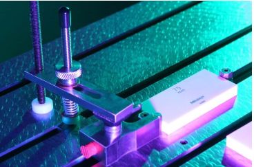
Figure 4: Gauge block set up as standard on universal measuring machine.
Line Scales (Rules, Stage Micrometers, Surveying Tapes)
Line scales in the form of stage micrometers as used in the calibration of eyepiece graticules and microscopes, precision linear scales, glass rules, steel rules, tapes and staffs are calibrated for length.
The accuracy to which these scales can be calibrated depends on:
- The material and form of the scale.
- The nature of the surface on which the lines are ruled.
- The quality of the lines.
For the highest accuracy precision scales, the SIP 214B will be used. The machine incorporates:
- A laser interferometer for the linear scale which supplies the traceability link.
- An electronic microscope as the locking device on the individual lines.
- A thermocouple for measuring the temperature of the line scale.
Steel rules up to 2000 mm are calibrated against a laser interferometer, while supported on a flat surface. Precision surveying tapes and wires of up to 50 m are calibrated for the length in catenary under a specified tension. The rate of change with tension of tapes or wires can also be calibrated. The tape material and the value for the tension weights must be submitted. For the tension weights the value for gravity is taken as 9,80665 m/s2. Electronic Distance Meters (EDMs) are calibrated up to 50 m in the tape tunnel and against two base line positions, 50 metres and 500 metres. The base line positions are calibrated with differential GPS.
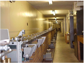
Figure 5: 50 metre tape tunnel used for Tapes, EDMs and Rules.
Optical Flats and Optical Parallels
Optical flats and parallels are used for calibrating flatness and parallelism of most measuring anvils, for example micrometer anvils. The optical flats and parallels are measured with a Zygo GPI interferometer, using a He-Ne laser light source; wavelength 632 nm. The master optical flat is calibrated using the “three flat method” where three optical flats are calibrated against each other, two at a time. The absolute flatness of each flat is calculated using separation of errors technique. Optical parallels are calibrated for both flatness and parallelism on the Zygo interferometer.
Mirrors can also be calibrated for flatness, as well as 90° prisms (penta prisms) and corner cubes for which an individual uncertainty is calculated.
Roundness Standards
Roundness standards and magnification standards are calibrated for roundness on the Talyrond 73 and the Talyrond 595.
Hemispheres are calibrated on the Talyrond 73 using an error separation technique where the hemisphere is measured and then moved through a specified angle (30°) and re-measured. This is repeated till a full circle is completed, resulting in 144 readings. These readings are entered into a matrix which separates the errors of the hemisphere from the spindle errors. Magnification standards are calibrated on the Talyrond 595.
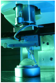
Figure 6: A glass hemisphere is calibrated on the Talyrond 73.
Surface Texture Standards
Surface texture and step height standards are calibrated on a Form Talysurf Series 2 measuring machine. The Form Talysurf is calibrated using a calibration ball of 22 mm in diameter. The Talysurf has a resolution of a low 0,2 nm over the full range of 10 mm.
Parameters required for the surface texture calibration must be clearly specified during contract review but currently the laboratory is only accredited for Ra and Rt parameters.
The Form Talysurf can also measure radii and angle on small surfaces, for example moulds and dies. The surface texture on curved objects can also be measured.
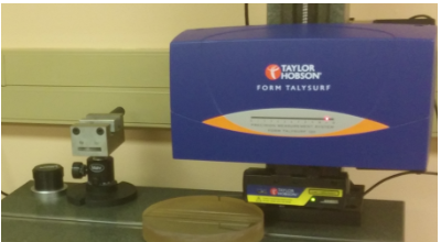
Figure 7; Form Talysurf with 10 mm travel in z axis down to 0,2 nm resolution and 120 mm travel in x axis.
Angle Standards
All angle calibrations are performed using a Moore Index Table interferometer. The NMISA has 2 index tables, one with 1440 teeth and the other 2160. This allows one to move the tables at 15 minute and 10 minute intervals respectively. If used in combination it can be moved at 5 minute intervals.
The tables are calibrated by using an error separation technique as is the method used for the calibration of the roundness standard; the standard glass hemisphere. The autocollimators are calibrated on a small angle generator which incorporates a laser interferometer.
The use of a phase shifting flatness interferometer in place of the autocollimator is used in special applications. The interferometer shows very good repeatability and overall accuracy, compared to the autocollimator.
The calibration of levels is also performed on a small angle generator against a laser interferometer
Co-Ordinate Metrology
Description to follow...
DEA Global Image CMM
The DEA Global Image CMM has a measuring volume of 2000 mm x 900 mm x 800 mm and is fitted with a Renishaw PH10MQ indexable probe head.
Two probing systems, a TP200 touch trigger probe and a SP600M continuous scanning probe, are available. The CMM is equipped with applicable stylus changers for use with the available probing systems.
Each of the three measuring scales (X, Y, Z) of the CMM is equipped with temperature sensors which record the temperature during measurement together with a part temperature sensor which enable the software/machine controller to perform temperature compensation. The coefficient of thermal expansion (CTE) for the machine scales are 10,5 x 10⁻⁶ /°C.
The measurement software used with this CMM is PC-DMIS CAD++ from Hexagon and can be used for manual and DCC measurements. Measurements according to CAD models can be done and are very useful for the automotive industry. PC-DMIS Gear software is used for the dimensional inspection of gears according to various gear standards (AGMA, DIN, etc.)
The CMM is mainly used for the evaluation of manufactured components according to specified tolerances as well as to provide the required data for reverse engineering purposes.
Accuracy Specifications
Uncertainties of measurement
Linear measurements = ± (2,4 + 3L) µm
GD&T measurements = ± 2,4 µm
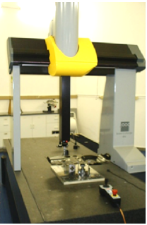
Figure 8; DEA Global Image CMM
UMAP103 micro-CMM
The micro-CMM has a measuring volume of 245 mm x 200 mm x 175 mm. Two probing systems, a Renishaw TP200 touch trigger probe and a UMAP103 fibre optic touch probe with a diameter of 35 μm can be used as well as a vision/camera system for non-contact measurement.
The measurement software used is MCOSMOS for contact measurements and VISIONPAK for non-contacting measurements.
The μCMM is used to measure various micro-parts and for the calibration of standards, for example: hardness indenters, acoustic microphones, and optical apertures.
Accuracy Specification
MPEE (TP200) = ± (2,0 + 3L) µm
MPEP = ± 1,9 µm
MPEE (Vision) = ± (0,8 + 2L) µm
UMAP103REP = ± 0,1 µm
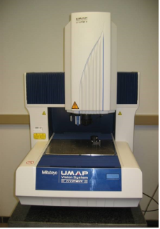
Figure 9; UMAP Micro-CMM
Zeiss Prismo Ultra CMM
The Zeiss Prismo Ultra CMM is the latest addition to NMISA and is the first and only CMM of its class in Africa. The CMM has a measuring volume of 1300 mm x 900 mm x 700 mm and is fitted with a VAST Gold probe head.
The VAST Gold pobe head can be used for point-to-point measurements as well as for 3D scanning. The probe head is equipped with an integrated navigation system to automatically determine the optimum scan speed and point density during scanning an GD&T measurements. The CMM is equipped with a stylus changer for use with the available stylus systems.
The measurement scales of the three axis (X, Y, Z) are manufactured of Zerodur with a CTE of 0,01 x 10⁻⁶ /°C. Temperature sensors record the part temperature during measurement which enables the software to perform temperature compensation.
The measurement software used is Calypso for general measurements and scanning. Gear-Po software is used for the inspection of gears and calibration of master gears. AFM Gauge-Check software is used for comparative calibrations of length standards and diameter standards.
This high accuracy CMM is mainly used for the calibration of step gauges, length bars, ring and plug gauges, squares, involute gears and master parts.
Accuracy Specification
MPEE = ± (0,55 + L/500) µm
Uncertainties of measurement
Step Gauge calibration = ± (0,3 + 1 x 10⁻⁶ x L) µm
Ring/Plug gauge calibrations =0,4 µm
GD&T measurements = ± 0,55 µm
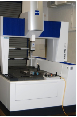
Figure 10; Zeiss Prismo Ultra CMM
Leica laser tracker CMM
This CMM laser tracker is mainly used onsite where large parts have to be measured. The micro-CMM has a measuring volume of 245 mm x 200 mm x 175 mm.
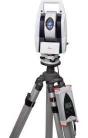
Figure 11; Leica Laser tracker CMM
Etalon Laser tracer
Etalon AG (Braunschweig, Germany) developed Absolute Multiline Technology for use in the precision measurement of lengths up to 20 m. This worldwide unmatched measuring technology combines the advantages of an interferometer for very high resolution and very good metrological traceability with those of absolute measuring systems. Unlike conventional interferometers, the laser beam of Absolute Multiline Technology can be interrupted at any time without causing precision loss.
Thanks to these worldwide unique system properties, this patented technology takes metrology automation in production to a new level. Integrated into a large machine tool, Absolute Multiline Technology continuously monitors machine calibration and initiates compensating measures as needed to ensure the dimensional accuracy of the components. Even automated metrology monitoring of robots based on reference lines is possible. And last but not least.
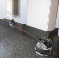
Figure 13; Laser tracer
ROMA articulated arm
3D digitizing, 3D modelling, point cloud inspection, reverse engineering, rapid prototyping or copy milling: this system is an all-purpose metrology tool for a multitude of applications.
Freedom of movement: with a fully integrated and certified RS3 laser scanner, this is an all-purpose metrology system for almost any measurement need. Point cloud inspection, product benchmarking, reverse engineering, rapid prototyping, virtual assembly or CNC milling are just some of the typical laser scanning applications that can be added to the rich portfolio of touch-probe measurement applications. The integrated laser scanner is designed to capture data from almost any object surface.
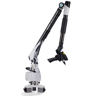
Figure 13; ROMA articulate measuring arm
SRS ball bar system
http://www.inora.com/products/inora-srs_volumetric_check/
The INORA SRS (Spatial Reference System) dramatically speeds the process of maximizing machine accuracy and consistency. Created using our proprietary Math Engine, it is the first system of its kind to deliver reliable, error-free volumetric check; therefore, it eliminates compounding errors in the manufacturing process. Additionally, it requires no specific orientation, which expedites the setup and testing processes.
The system consists of six carbon-fibre bars — as well as four steel spheres — that connect to form a rigid tetrahedron. The symmetrical tetrahedron shape is the first of the Platonic solids and provides six easy-to-read comparisons. As a reference object, SRS is geometrically and thermally stable, meaning it can be used in almost any location or condition.
While many machine verification processes take three to five hours, SRS volumetric check averages between 10 and 30 minutes. With regular use and an automated setup, it may require even less time. Once SRS is placed in a machine’s workspace, the accompanying SRS software analyzes the data to verify alignment and accuracy.
Applications
- Verify production and measuring machines (machine tools, CMMs, robots, etc.).
- Correlate CMM and CNC machines to determine appropriate calibration cycles.
- Optimize CMM performance.
- Provide rapid checks of articulating-arm portable CMMs, laser trackers, systems, etc.
Figure 14; SRS ball bar system
Handheld Instruments
Handheld instruments such as Micrometers, Calipers and Dial Test Indicators are calibrated at NMISA. External micrometers with a range from 0 – 25 mm are calibrated against gauge blocks. Calipers, both digital and Vernier, with a range from 0 – 600 mm are calibrated against a step gauge.
Dial test indicators with a range from 0 – 25 mm are calibrated against a Dial Gauge Tester.
The team
Contact Us
Email us at:
length@nmisa.org or
calibrationoffice@nmisa.org